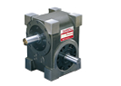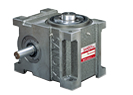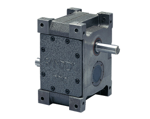
The E Series (Parallel shaft type) is an oscillating drive that uses a parallel cam mechanism with parallel input and output shafts. This mechanism makes it possible to produce drives with large oscillating angles.
Parallel Shaft Type
Unlike other SANDEX indexers, the input and output shafts on a P Series indexer are parallel.
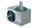
Large Oscillating Angles
Drives can be developed with large oscillating angles.
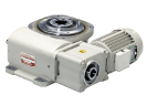
Flexible Mounting Positions
Index mounts in any position with gearmotor mounting on either side of the index.
- Motor coil winders
- Conveying mechanism for plastic container forming machines
- Drive for linear motions in automatic machinery
E Series (Parallel shaft type) Specifications
| Description | Symbol | Unit | P40/E40 | P50/E50 | P65/E65 | P80/E80 | P100/E100 | P125/E125 |
| P - Indexing Stops | s | 1, 2, 3, 4, 6, 8 | ||||||
| E - Oscillating Angle | φ | deg | 15, 30, 45 | |||||
| Indexes per Minute | ipm | 0 to 300 | ||||||
| Standard Cam Curve | Modified Sine (MS), Modified Constant Velocity (MCV) | |||||||
| Output Allowable Thrust Load | P1 | N | 637 | 1274 | 2450 | 3528 | 4704 | 5096 |
| Output Allowable Radial Load | P2 | N | 490 | 980 | 1568 | 2450 | 3920 | 6174 |
| Output Static Torque | Ts | N・m | Refer to Torque Transfer Table | |||||
| Output Torsional Rigidity | K1 | N・m/ rad |
2.0×10³ | 4.3×10³ | 9.0×10³ | 1.81×10⁴ | 3.19×10⁴ | 4.93×10⁴ |
| Output Moment of Inertia | J0 | kg・m2 | Refer to Torque Transfer Table | |||||
| Input Allowable Thrust Load | P4 | N | 637 | 1274 | 2450 | 3528 | 4704 | 5096 |
| Input Max Repetitious Bending Force | P5 | N | 490 | 980 | 1568 | 2450 | 3920 | 6174 |
| Input Max Repetitious Allowable Torque | P6 | N・m | 29.4 | 58.8 | 107.8 | 245 | 392 | 637 |
| Input Torsional Rigidity | K2 | N・m/ rad |
2.0×10³ | 4.3×10³ | 9.0×10³ | 1.81×10⁴ | 3.19×10⁴ | 4.93×10⁴ |
| Input Moment of Inertia (Note 1) | J1 | kg・m2 | 1.5×10⁻⁴ | 2.75×10⁻⁴ | 8.25×10⁻⁴ | 2.45×10⁻³ | 6.0×10⁻³ | 1.63×10⁻² |
| Indexing Accuracy (1 Dwell) (1, 2, 3, 4 stops) |
sec | ±90 | ±72 | ±60 | ±60 | ±60 | ±60 | |
| Indexing Accuracy (2 Dwell) (6, 8 stops) |
sec | ±180 | ±144 | ±120 | ±120 | ±120 | ±120 | |
| Repeatability | sec | 90 | 72 | 60 | 60 | 60 | 60 | |
| Product Weight | kg | Approx. 3.5 | Approx. 7.5 | Approx. 14 | Approx. 20 | Approx. 36 | Approx. 65 | |
| Housing Color | Hammer net gray | |||||||
| Lubrication | Grease lubrication | Grease lubrication | Oil lubrication | Oil lubrication | Oil lubrication | Oil lubrication | ||
| Output Configuration | Shaft | Shaft | Shaft | Shaft | Shaft | Shaft | ||
Note 1) Input moment of inertia: J is calculated in dwell.
| Description | Symbol | Unit | P150/E150 | P175/E175 | P200/E200 | P250/E250 | P320/E320 | P400/E400 |
| P - Indexing Stops | s | 1, 2, 3, 4, 6, 8 | ||||||
| E - Oscillating Angle | φ | deg | 15, 30, 45 | |||||
| Indexes per Minute | ipm | 0 to 300 | ||||||
| Standard Cam Curve | Modified Sine (MS), Modified Constant Velocity (MCV) | |||||||
| Output Allowable Thrust Load | P1 | N | 7350 | 9016 | 12936 | 15190 | 22540 | 26460 |
| Output Allowable Radial Load | P2 | N | 8428 | 9800 | 13524 | 15288 | 23520 | 39200 |
| Output Static Torque | Ts | N・m | Refer to Torque Transfer Table | |||||
| Output Torsional Rigidity | K1 | N・m/ rad |
1.76×10⁵ | 1.65×10⁵ | 3.19×10⁵ | 5.26×10⁵ | 1.08×10⁶ | 1.46×10⁶ |
| Output Moment of Inertia | J0 | kg・m2 | Refer to Torque Transfer Table | |||||
| Input Allowable Thrust Load | P4 | N | 7350 | 9016 | 12936 | 15190 | 22540 | 26460 |
| Input Max Repetitious Bending Force | P5 | N | 8624 | 9800 | 18620 | 23520 | 41160 | 54880 |
| Input Max Repetitious Allowable Torque | P6 | N・m | 1323 | 1813 | 3136 | 4900 | 10780 | 14700 |
| Input Torsional Rigidity | K2 | N・m/ rad |
1.76×10⁵ | 1.65×10⁵ | 3.19×10⁵ | 5.26×10⁵ | 1.08×10⁶ | 1.46×10⁶ |
| Input Moment of Inertia (Note 1) | J1 | kg・m2 | 4.0×10⁻² | 7.5×10⁻² | 0.148 | 0.495 | 1.7 | 4.43 |
| Indexing Accuracy (1 Dwell) (1, 2, 3, 4 stops) |
sec | ±60 | ±60 | ±60 | ±60 | ±60 | ±60 | |
| Indexing Accuracy (2 Dwell) (6, 8 stops) |
sec | ±120 | ±120 | ±120 | ±120 | ±120 | ±120 | |
| Repeatability | sec | 60 | 60 | 60 | 60 | 60 | 60 | |
| Product Weight | kg | Approx. 100 | Approx. 160 | Approx. 220 | Approx. 350 | Approx. 750 | Approx. 1400 | |
| Housing Color | Hammer net gray | |||||||
| Lubrication | Oil lubrication | Oil lubrication | Oil lubrication | Oil lubrication | Oil lubrication | Oil lubrication | ||
| Output Configuration | Shaft | Shaft | Shaft | Shaft | Shaft | Shaft | ||
Note 1) Input moment of inertia: J is calculated in dwell.
Options for the E Series (Parallel shaft type)
| Description | Symbol | Unit | P40/E40 | P50/E50 | P65/E65 | P80/E80 | P100/E100 | P125/E125 |
| Mounted Reducer | R type | Special | R48 | R48 | R48, R65 | R65, R80 | R80 | |
| Mounted Cam Balancer | B type | Special | Special | Special | Special | Special | Special | |
| Mounted TorqueLimiter | TF and TC types | 4, 5 | 6 | 6 | 6, 7 | 7, 8 | 7, 8 | |
| Mounted Torque Limit Overload Sensor | Available | Available | Available | Available | Available | Available | ||
| Mounted Motor | Special | Special | Special | Special | Special | Special | ||
| Mounted Timing Cam | Special | Special | Special | Special | Special | Special | ||
| Different Oil Fill/Drain Position | - | - | Available | Available | Available | Available | ||
| Knock Pin Holes in Housing | Available | Available | Available | Available | Available | Available | ||
| Different Input/Output Shaft Configuration | Available | Available | Available | Available | Available | Available | ||
Contact for further details.
| Description | Symbol | Unit | P150/E150 | P175/E175 | P200/E200 | P250/E250 | P320/E320 | P400/E400 |
| Mounted Reducer | R type | R80, R100 | R100 | R100, R125 | R125, R160 | R160 | R48, R65 | |
| Mounted Cam Balancer | B type | Special | Special | Special | Special | Special | Special | |
| Mounted TorqueLimiter | TF and TC types | 8, 11 | 11, 14 | 11, 14 | 14, 18 | 18 | 6, 7 | |
| Mounted Torque Limit Overload Sensor | Available | Available | Available | Available | Available | Available | ||
| Mounted Motor | Special | Special | Special | Special | Special | Special | ||
| Mounted Timing Cam | Special | Special | Special | Special | Special | Special | ||
| Different Oil Fill/Drain Position | Available | Available | Available | Available | Available | Available | ||
| Knock Pin Holes in Housing | Available | Available | Available | Available | Available | Available | ||
| Different Input/Output Shaft Configuration | Available | Available | Available | Available | Available | Available | ||
Contact for further details.