Welding Positioners for Greater
Space-Savings and Higher Productivity
Space-Savings and Higher Productivity
SP Series(6 models)
| SP030 | SP030H | SP060 |
| SP120 | SP240 | SP360 |
| SP120 | SP240 | SP360 |
Payload:300kg to 3,600kg
Large hollow bore:Φ245mm(SP360)
Thin-profile body:190mm(SP030 to SP060)
Repeatability:± 0.03mm(SP030 to SP120:R=250mm position)
Excellent stability and ensure shortening the takt time
Tough against impact from emergency stops
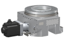
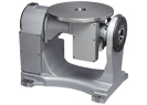
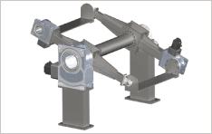
Cantilever-mounted 2-axis
welding positioner
welding positioner
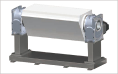
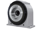
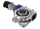
BBQ welding positioner
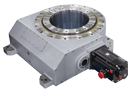
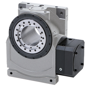
Horizontal single-axis
welding positioner
welding positioner
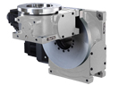
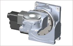
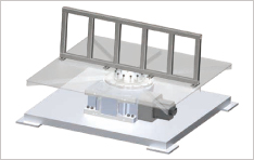
Ferris-wheel type
welding positioner
welding positioner
| Model | SP030 | SP030H | SP060 | SP120 | SP240 | SP360 | |
| Allowable payload | kg | 300 | 300 | 600 | 1,200 | 2,400 | 3,600 |
| Output table diameter | mm | 155 | 155 | 155 | 220 | 260 | 335 |
| Output hollow diameter | mm | 120 | 120 | 120 | 170 | 170 | 245 |
| Gear ratio | 140 | 56 | 140 | 120 | 126 | 168 | |
| Maximum rotating speed | min-1 | 30 (180°/sec) |
60 (360°/sec) |
30 (180°/sec) |
20 (120°/sec) |
20 (120°/sec) |
20 (120°/sec) |
| Repeatability | mm | ±0.03 (R=250mm) |
±0.03 (R=250mm) |
±0.03 (R=250mm) |
±0.03 (R=250mm) |
±0.05 (R=500mm) |
±0.05 (R=500mm) |
| Momentary max. allowable torque |
N・m | 1,900 | 1,160 | 2,720 | 6,900 | 9,400 | 12,700 |
| Start / Stop limit torque | N・m | 875 | 510 | 1,350 | 1,960 | 5,150 | 9,580 |
| Allowable moment load*1 | N・m | 1,095 | 850 | 1,795 | 7,360 | 10,800 | 15,100 |
| Internal moment of inertia at the input shaft*2 |
kg・m2 | 3.73×10⁻⁴ | 4.20×10⁻⁴ | 3.73×10⁻⁴ | 1.667×10⁻³ | 4.340×10⁻³ | 6.530×10⁻³ |
| Recommended motor capacity*3 |
kW | 1 | 1 | 1.5 | 2 | 5.5 | 7.5 |
| Paint color | N1.5 (Black) |
N1.5 (Black) |
N1.5 (Black) |
N1.5 (Black) |
N1.5 (Black) |
N1.5 (Black) |
|
| Net weight | kg | 120 | 120 | 120 | 270 | 545 | 780 |
*1 Allowable moment load depends on the mounting direction and payload.
For details, please refer to the allowable moment diagrams on pages 8 to 10.
*2 Internal moment of inertia at the input shaft depends on the attachment code.
For details, please refer to the attachment code selection table on page 7.
*3 Recommended motor capacity value is reference only. It depends on the operating conditions.