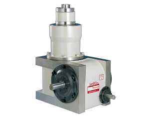
The output has a flange for an indexing table, and another hollow table mounting flange for processing units. The internal mechanism is similar to the DA Type but instead of the continuous drive shaft, the table mounting flange is stationary and hollow to allow wiring and air lines to be stored for easier maintenance and servicing.
Double Coaxial Output Design
Features a coaxial output with indexing shaft and hollow stationary shaft. Ideal for driving rotary base assembly machines.
High Accuracy
The intermittent indexing motion is produced by a roller gear cam for precision positioning.
- Assembly and inspection machines for automotive components
- Assembly and inspection machines for electronic components
- Use as base chassis or main drive unit for various automated machines.
DB Series Specifications
| Input Characteristics | ||||||
| Characteristic | Symbol | Unit | 14DB | 20DB | 25DB | |
| Reducer Input Shaft | Allowable Thrust Load | C12 | N | 1078 | 980 | 1176 |
| Max Repeated Bending Force | C13 | N | 1078 | 1568 | 1960 | |
| Max Repeated Allowable Torque | C14 | N・m | 225.4 | 343 | 784 | |
| Torsional Rigidity | K8 | N・m/rad | 1.54×10⁴ | 2.55×10⁴ | 7.45x10⁴ | |
| Inertia Moment | J2 | kg・m2 | 1.1×10⁻³ | 2.38×10⁻³ | 3.0×10⁻³ | |
| Other Information | Product Weight | kg | Approx. 150 | Approx. 375 | Approx. 545 | |
| Paint Color | Emerite Satin 5Y7/1 | |||||
| Oil Volume | L | Approx. 6 | Approx. 14 | Approx. 22 | ||
Note 1) Input moment of inertia: J is calculated in dwell.
| Output shaft characteristics | ||||||
| Characteristic | Symbol | Unit | 14DB | 20DB | 25DB | |
| Cam Shaft | Allowable Thrust Load | C9 | N | 2940 | 4900 | 5782 |
| Max Repeated Bending Force | C10 | N | 3675 | 7546 | 8722 | |
| Max Repeated Allowable Torque | C11 | N・m | 588 | 1274 | 1764 | |
| Torsional Rigidity | K6 | N・m/rad | 1.37×10⁵ | 2.65×10⁵ | 4.31×10⁵ | |
| Moment of Inertia (Note 1) | J1 | kg・m2 | 4.5×10⁻² | 0.116 | 0.565 | |
| Hollow Fixed Shaft | Allowable Thrust Load | C1 | N | 8134 | 13720 | 18620 |
| Allowable Radial load | C2 | N | 3822 | 8820 | 14700 | |
| Max Repeated Allowable Torque | C3 | N・m | 980 | 1960 | 2254 | |
| Torsional Rigidity | K3 | N・m/rad | 1.37×10⁵ | 3.53×10⁵ | 4.61×10⁵ | |
| Intermittent Rotary Shaft | Allowable Thrust Load | C7 | N | 9800 | 15680 | 16660 |
| Allowable Radial load | C8 | N | 15680 | 28420 | 36260 | |
| Allowable Torque | TS | N・m | Refer to Torque Transfer Table | |||
| Torsional Rigidity | K4 | N・m/rad | 8.13×10⁵ | 5.88×10⁶ | 4.9×10⁶ | |
| Inertia Moment | J0 | kg・m2 | 9.4×10⁻² | 0.515 | 1.10 | |
| Indexing Accuracy | Seconds | ±30 | ±30 | ±20 | ||
(1N ≒ 0.102 kgf)